Discussion of TABC-related matters
-
SteveW
- Posts: 324
- Joined: Sun Aug 23, 2015 8:25 am
- Location: Nottingham, UK
Post
by SteveW » Sat Oct 22, 2016 3:19 am
I didn't want to hijack the steering thread any more, so I though that I would answer Marv's question to me about my differential set up in a new thread. It also makes it easier to find if its of use to anyone else. To recap, Marv asked how I set up my differential...
A brief summary of what I did is included in an article that I wrote for the current edition of TTT2. This is the link to it:
http://ttypes.org/ttt2/restoration-of-tc8485-part-2
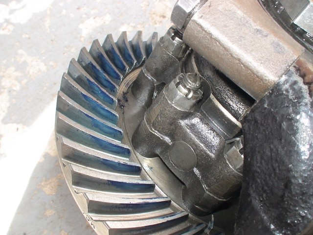
In brief, I set the preload according to the 'Blower' workshop manual. i.e. by tightening the ball race nuts to just pinch the ball race inner tracks and then tightening the off side one a further serration before inserting the lock screw. I tested the backlash by clamping the prop shaft end of the diff so that it couldn't move relative to the casing and then rocking the crown wheel backwards and forwards, measuring the movement with a vernier caliper. If its not within tolerance (0.007 to 0.010 inch) then the crown wheel can be adjusted laterally by adjusting the ball race nuts (tightening one and loosening the other by the same amount moves the crown wheel left or right with respect to the centre line of pinion). Finally, I tested it with engineers blue, if its adjusted correctly it should end up looking like this (matches the drawing in Blower).
-
Marv
- Posts: 242
- Joined: Sat Oct 03, 2015 7:34 pm
Post
by Marv » Sat Oct 22, 2016 5:38 am
Thanks Steve: I just finished the run-out testing and torque up of new HT bolts and Aerotite nuts on the crown wheel yesterday, Then adjusted the nuts on the new tapered roller bearings and made a set-up to measure 5-7 in-lbs breakaway torque. Today, I will be calculating the thickness of spacers I need to set the crown wheel to pinion interface. Once done, then I'll blue the teeth and adjust the crown wheel lateral movement to achieve the tooth to tooth mesh pattern as you did.
-
Duncan M
- Posts: 855
- Joined: Fri Oct 10, 2014 9:08 pm
- Location: Northern California
Post
by Duncan M » Sat Oct 22, 2016 12:12 pm
The TC differential used the oil scroll type "seal" to keep the oil inside-- where the differential input shaft rotates. I guess few of these oil scrolls have survived on TC's. I can;t be the only one? The scrolls were among the things to be damaged if or when the original pinion carrier (double row ball) bearing let loose, which was caused by the disintegration of the bronze or brass ball cages of the bearing. The "seal" is just aft of where the driveshaft connects to the differential. Pics to give a general idea of that oil scroll and location. This is where a modern lip seal conversion takes place. Pics from TC9866. This oil scroll is undamaged.
No doubt the tapered roller bearing conversion adds to the integrity of the differential in a hot rod situation, but the original oil scroll seal does work nearly flawlessly when in an undamaged condition, at least as far as for preventing drips. The intent of the modern lip seal is to also keep dirt and grime from entering.
https://fromtheframeup.com/uploads/TT_C ... Set_Up.pdf
Duncan MacKellar-
TC9866
N. California
Last edited by
Duncan M on Wed Dec 06, 2017 3:13 pm, edited 3 times in total.
-
Marv
- Posts: 242
- Joined: Sat Oct 03, 2015 7:34 pm
Post
by Marv » Sat Oct 22, 2016 12:22 pm
Yep, it was the first thing milled off to incorporate the new metal cone that accepts the modern rubber lip seal. My scroll looked to be in good shape and I couldn't really see much evidence of front cone leakage in that area so you are probably right that it did do a pretty fair job in it's basic design. I doubt that area saw a lot of oil anyway and what was there certainly wasn't under pressure. New tapered roller bearings, new lip seal, ...... migrated a bit into the present day technology.
-
Duncan M
- Posts: 855
- Joined: Fri Oct 10, 2014 9:08 pm
- Location: Northern California
Post
by Duncan M » Sat Oct 22, 2016 1:31 pm
Marv-
Yes, when the diff is filled to the original correct level with oil, the pinion carrier bearings (old or new tapered style) are sitting in only 1/8 inch or so of oil when the car is level. A critical oil level! Pinion to crown wheel gear lash is adjusted entirely by shims only when the original style bearings (non tapered) are used or replaced. Pic shows entire pinion carrier assembly (and shims) that resides in the nose of the diff.
-
Marv
- Posts: 242
- Joined: Sat Oct 03, 2015 7:34 pm
Post
by Marv » Sat Oct 22, 2016 2:26 pm
Just finished doing the set-up, calculations and measurements today for my pinion the crown wheel interface. The unit had a .020" shim originally, I purchased a .060" shim from Roger Furneaux as being the most common when converting to tapered rollers. When all was said and done. I need .085" total in shims, I'm making a .005" brass shim tonight after dinner. Should be good to go tomorrow.
-
Marv
- Posts: 242
- Joined: Sat Oct 03, 2015 7:34 pm
Post
by Marv » Mon Oct 24, 2016 11:41 am
Steve, et al...
I think I've got it whipped. CW&P backlash set to .0065". New tapered roller bearings installed, pinion shim is .060" It fell within .002" of the calculations from Roger Furneaux's setup instructions, Pre-loads are set. Don't think I can make it much better. Prussian blue test yielded the following results which meets the brown book, Blower and Roger's instructions and diagrams. Time to button it up!
-
SteveW
- Posts: 324
- Joined: Sun Aug 23, 2015 8:25 am
- Location: Nottingham, UK
Post
by SteveW » Tue Oct 25, 2016 2:50 am
Hi Marv, just a quick observation on your picture compared to mine. The nuts on yours don't have split pins through them. Have you locked the nuts in another way (e.g. with thread lock)? After all that hard work, the last thing that you want to do is for them to loosen off when in use.
-
Marv
- Posts: 242
- Joined: Sat Oct 03, 2015 7:34 pm
Post
by Marv » Tue Oct 25, 2016 4:46 am
They're HT Aerotite self locking HT nuts, bolts and washers from Roger Furneaux. Torqued in 3 steps 12 - 12 - 6 to 30 ft.-lbs in a cris-cross pattern.
-
Richard Michell
- Posts: 89
- Joined: Sun Jul 05, 2015 2:39 pm
Post
by Richard Michell » Tue Oct 25, 2016 12:43 pm
Marv, re your engagement pattern, although nicely central top to bottom, it seems close to the inner edge. Out of interest, what was the pattern on the other side when you reversed the turning direction? I acknowledge that near the inner edge is much preferable to the outer but in doing mine recently I did adjust to be more centralized than your pattern. SteveW's engagement seems a little further in from the edge.
-
Marv
- Posts: 242
- Joined: Sat Oct 03, 2015 7:34 pm
Post
by Marv » Tue Oct 25, 2016 1:33 pm
Pretty much the same on the reverse side too Richard. If you'll notice there is a heavy line of Prussian blue at the root and the leading edge of the teeth and the central area is filmed thinner by contact. I used too much bluing and the heavy lines are where the bluing squeezed out and left a heavier undisturbed line. I may run the test again before I button it into the axle housing as a final check.