MG TA - Centralised Lubrication System
(valid TA2258 onwards)
by Ian Linton
During the current restoration of TA3120 I have found it necessary to restore this system, mostly with new parts. This was because the entire kits for the rear trunnions were missing, and most of the remaining pipes were damaged beyond repair. I also should have taken more photos of the fine detail during dismantling for future routing purposes.
To summarise,
1. Components -- a full listing is in the Service Parts List (I have a replica bought at a a MGCC T-Register Rebuild) Page 60 for the Grouped Nipple Chassis Lubrication System. This gives lengths of 2'10", 5'8" and 8'9" for the tubing.
2. Tubing - 3/16" x 20 gauge bought from Namrick in Brighton, UK. Two 25 foot rolls are more than enough. The outer diameter is within a gnat's whisker of the original piping, although it looks larger because it is clean and new. The pipe comes with a line of black print on it but this comes off with a fierce rubbing using a cloth and white spirit. Spare pipe can possibly be used for the carburettor float bowl overflow lines.
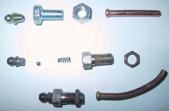
3. Olives - I have not used these as I discovered my pipe flaring kit has a 3/16" die which makes ends which suit all the adapters just fine. The pipe ends need a little gentle filing or sanding to remove the surface marks created in the flaring operation as the original nuts are a tight fit on the new tubing. Not strictly original, but invisible when made up. See photo (noting that both tubes shown have flared ends, one new tube and one original tube tested for feasibility).
4. Oilers - TA3120 was missing two, so I have made up substitutes (not replicas, but close enough for now) using a plated M8 x 1.0 (= Metric Fine) bolt having thread length 16 mm, drilled through with 2.5mm hole, then counter-drilled similar to an original oiler. This seems to work fine, even though the threads seem strange for an MG T-type. The oiler threads, securing half nuts, brass nuts etc, clean up nicely with M8 x 1.0 taps and dies. I've not fitted grease nipples yet, but note that the originals have separate balls and springs inside the adapter body, not captive in the grease nipples as more usual nowadays. See photo.
5. Rear Trunnion elbow - Not available but a restorer in the USA has converted a modern fitting to an excellent replica, although not for sale. I may have a go later, but for now will connect this line direct to the trunnions (see Clausanger Page 20). Again the M8 x 1.0 comes to the rescue as a suitable BSF thread can be turned down at one end to give several turns to suite the original brass nut. Drilling through will provide the required adapter.
6. Routing - Sherrell has an illustration on Page 255 which shows a line of spare holes which he refers to as "probably pre-war greaser mounts". Clausanger has several photos which show parts, Pages 18, 19 and 20. The three tubes from the oilers first pass through a flattened brass P-clip bolted halfway down the foot ramp support. All piping then goes onto the outside of the chassis. Most of the routing can be seen in the excellent illustration in the "TA & TC Gold Portfolio" book, pages 28 and 29, including a detailed sketch of the rear trunnion arrangement.
Acknowledgements: Lee Jacobsen (routing), Tom Metcalf (rear elbow)
Ian Linton (TA3120) Lewes, East Sussex, UK
